Hi David,
I thought you have Brush Servos on your systems? If this is the case SnapAmp is operating in torque mode. KFLOP commands SnapAmp to apply a motor current. Basically all motors operate in torque mode at some level. The torque is controlled to move the motor to some position based on encoder feedback. The issue is whether some external drive closes the position loop and is just told the desired position or whether the Controller (in this case KFLOP) performs the feedback loopto move to the desired position.
HTH Regards TK
| Group: DynoMotion |
Message: 12156 |
From: David Stevenson |
Date: 8/26/2015 |
| Subject: Re: Operating Servos in Torque Mode with SnapAmp |
Hi Tom,
They are brushless servos on my systems.
Is there a way to cap the torque which should be applied, but not
have this be the point where the SnapAmp faults? You had noted
previously that the MaxOutput value could be changed to limit the
current, but this seemed to make the motors turn slowly and fault
when the value was hit. Is this the best variable to adjust to set
the applied torque in a fluid situation?
Thanks for your help,
David.
On 8/26/2015 1:49 PM, Tom Kerekes
tk@... [DynoMotion] wrote:
Hi David,
I thought you
have Brush Servos on your systems? If this is the
case SnapAmp is operating in torque mode. KFLOP
commands SnapAmp to apply a motor current. Basically
all motors operate in torque mode at some level. The
torque is controlled to move the motor to some
position based on encoder feedback. The issue is
whether some external drive closes the position loop
and is just told the desired position or whether the
Controller (in this case KFLOP) performs the feedback
loopto move to the desired position.
HTH
Regards
TK
| Group: DynoMotion |
Message: 12159 |
From: Tom Kerekes |
Date: 8/26/2015 |
| Subject: Re: Operating Servos in Torque Mode with SnapAmp |
Hi David,
SnapAmp drives Brushless motors in Voltage mode.
When the voltage limit is reached the motor will be not able to move sufficiently and there will be a following error. If the Max Following Error is exceeded the Axis will fault. Setting the Max Following error to a huge value should avoid the fault.
Motor Voltage is required to overcome motor back-emf (voltage that the motor generates like a generator when spinning) and motor resistance to cause current to flow. One approach might be to continuously monitor the motor speed and compute the expected motor back-emf. Then change the Max Output to be some amount higher than this. For example: If we measure the motor speed (from the rate of change of the encoder) to be 500RPM. We might then determine the back-emf to be 10V. If we then limit the Output to 11V then if the motor resistance is 0.2 Ohms then the current would be limited to 5 Amps.
Do you think you would like to try this?
Regards TK
| Group: DynoMotion |
Message: 12160 |
From: David Stevenson |
Date: 8/26/2015 |
| Subject: Re: Operating Servos in Torque Mode with SnapAmp |
Hi Tom,
That sounds very interesting. I would expect some formulas could be
developed to set this up in a C program? Where you note monitor the
speed and compute the back-emf, does that back-emf increase in a
linear manner as the loading increases?
I would very much like to try this approach.
Thank you,
David.
On 8/26/2015 4:19 PM, Tom Kerekes
tk@... [DynoMotion] wrote:
Hi
David,
SnapAmp drives
Brushless motors in Voltage mode.
When the
voltage limit is reached the motor will be not able to
move sufficiently and there will be a following
error. If the Max Following Error is exceeded the
Axis will fault. Setting the Max Following error to a
huge value should avoid the fault.
Motor Voltage
is required to overcome motor back-emf (voltage that
the motor generates like a generator when spinning)
and motor resistance to cause current to flow. One
approach might be to continuously monitor the motor
speed and compute the expected motor back-emf. Then
change the Max Output to be some amount higher than
this. For example: If we measure the motor speed
(from the rate of change of the encoder) to be
500RPM. We might then determine the back-emf to be
10V. If we then limit the Output to 11V then if the
motor resistance is 0.2 Ohms then the current would be
limited to 5 Amps.
Do you think
you would like to try this?
Regards
TK
| Group: DynoMotion |
Message: 12162 |
From: Tom Kerekes |
Date: 8/26/2015 |
| Subject: Re: Operating Servos in Torque Mode with SnapAmp |
Hi David,
Back-emf is created in the motor by speed not load.
Please perform some tests to gather some data and information.
Firstly verify that limiting the Max Output does limit the torque in a manner that works well for you at low speeds. Set the Max Following error to a huge value and set the Max Output to some value then move slowly into some obstruction. When pushing against an obstacle motor speed is basically zero so there is no back-emf to compensate for. As long as you don't move other than low speed does everything work as expected and desired?
If so, make and post some Step Response Screen long "Moves" at at least two relatively high speeds so we can see the required voltage (Output) to move at those speeds under minimal loads. Also save and post the raw data so we can plot it various ways to see Output, Speed, Current, etc... From those we should be able to determine the back-emf coefficient and so forth.
Regards TK
| Group: DynoMotion |
Message: 12165 |
From: David Stevenson |
Date: 8/26/2015 |
| Subject: Re: Operating Servos in Torque Mode with SnapAmp |
Hi Tom,
Thank you very much for your help! I will do some testing in the
morning and get you some results.
Best regards,
David.
On 8/26/2015 6:04 PM, Tom Kerekes
tk@... [DynoMotion] wrote:
Hi David,
Back-emf is created in the motor by speed not
load.
Please perform
some tests to gather some data and information.
Firstly
verify that limiting the Max Output does limit the
torque in a manner that works well for you at low
speeds. Set the Max Following error to a huge value and
set the Max Output to some value then move slowly into
some obstruction. When pushing against an obstacle
motor speed is basically zero so there is no back-emf to
compensate for. As long as you don't move other than
low speed does everything work as expected and desired?
If
so, make and post some Step Response Screen long "Moves"
at at least two relatively high speeds so we can see the
required voltage (Output) to move at those speeds under
minimal loads. Also save and post the raw data so we
can plot it various ways to see Output, Speed, Current,
etc... From those we should be able to determine the
back-emf coefficient and so forth.
Regards
TK
| Group: DynoMotion |
Message: 12169 |
From: David Stevenson |
Date: 8/28/2015 |
| Subject: Re: Operating Servos in Torque Mode with SnapAmp |
Hi Tom,
The MaxOutput does indeed limit the torque appropriately at low
speeds for the two axis.
I setup the Step Response for each axis to move at a speed which I
though might be a good operating speed and the data is attached.
Hopefully it is what you were looking for.
Thank you,
David.
On 8/26/2015 6:04 PM, Tom Kerekes
tk@... [DynoMotion] wrote:
Hi David,
Back-emf is created in the motor by speed not
load.
Please perform
some tests to gather some data and information.
Firstly
verify that limiting the Max Output does limit the
torque in a manner that works well for you at low
speeds. Set the Max Following error to a huge value and
set the Max Output to some value then move slowly into
some obstruction. When pushing against an obstacle
motor speed is basically zero so there is no back-emf to
compensate for. As long as you don't move other than
low speed does everything work as expected and desired?
If
so, make and post some Step Response Screen long "Moves"
at at least two relatively high speeds so we can see the
required voltage (Output) to move at those speeds under
minimal loads. Also save and post the raw data so we
can plot it various ways to see Output, Speed, Current,
etc... From those we should be able to determine the
back-emf coefficient and so forth.
Regards
TK
| Group: DynoMotion |
Message: 12174 |
From: Tom Kerekes |
Date: 8/28/2015 |
| Subject: Re: Operating Servos in Torque Mode with SnapAmp [4 Attachments] |
Hi David,
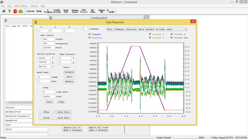
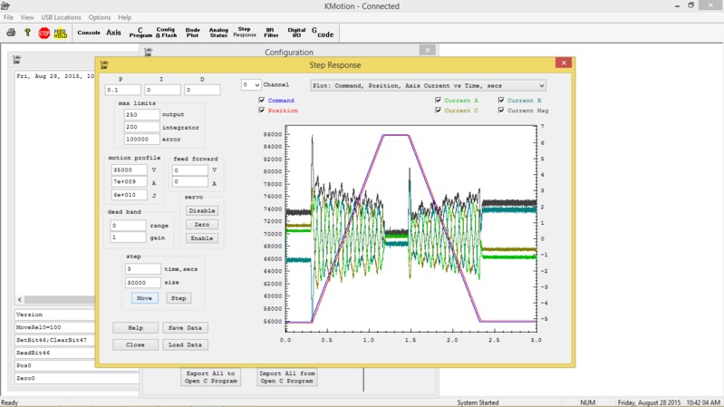
Based on these plots at that speed of 35000 counts/sec it looks to me like the back emf is requiring about 50 units of Output. The other 10-20 units of output is creating the motor current (torque) of 1.5 to 3,0 Amps.
Please do another set at half that speed (17500 counts/sec).
In the first test what value did you need to reduce the Max Output to in order to limit the torque?
Regards TK


From: "David Stevenson david.m.stevenson@... [DynoMotion]" <DynoMotion@yahoogroups.com>
To: DynoMotion@yahoogroups.com
Sent: Friday, August 28, 2015 7:57 AM
Subject: Re: [DynoMotion] Operating Servos in Torque Mode with SnapAmp [4 Attachments]
[Attachment(s) from David Stevenson included below]
Hi Tom,
The MaxOutput does indeed limit the torque appropriately at low
speeds for the two axis.
I setup the Step Response for each axis to move at a speed which I
though might be a good operating speed and the data is attached.
Hopefully it is what you were looking for.
Thank you,
David.
On 8/26/2015 6:04 PM, Tom Kerekes
tk@... [DynoMotion] wrote:
Hi David,
Back-emf is created in the motor by speed not
load.
Please perform
some tests to gather some data and information.
Firstly
verify that limiting the Max Output does limit the
torque in a manner that works well for you at low
speeds. Set the Max Following error to a huge value and
set the Max Output to some value then move slowly into
some obstruction. When pushing against an obstacle
motor speed is basically zero so there is no back-emf to
compensate for. As long as you don't move other than
low speed does everything work as expected and desired?
If
so, make and post some Step Response Screen long "Moves"
at at least two relatively high speeds so we can see the
required voltage (Output) to move at those speeds under
minimal loads. Also save and post the raw data so we
can plot it various ways to see Output, Speed, Current,
etc... From those we should be able to determine the
back-emf coefficient and so forth.
Regards
TK
| Group: DynoMotion |
Message: 12176 |
From: David Stevenson |
Date: 8/28/2015 |
| Subject: Re: Operating Servos in Torque Mode with SnapAmp [2 Attachments] |
Hi Tom,
I will do another test in the morning at the lower speed.
For the first test, I set MaxOutput to 25 for axis 0 and 15 for axis
1 (axis 0 wouldn't move at 15 because of friction.) This provided
enough torque to slowly move the slide axis, but barely move the
resisting material. I then reset MaxOutput to 250 for both axis to
perform the Step Response tests.
Thank you for your help,
David.
On 8/28/2015 3:23 PM, Tom Kerekes
tk@... [DynoMotion] wrote:
Hi
David,
Based on these
plots at that speed of 35000 counts/sec it looks to me
like the back emf is requiring about 50 units of
Output. The other 10-20 units of output is creating the
motor current (torque) of 1.5 to 3,0 Amps.
Please do
another set at half that speed (17500 counts/sec).
In the first
test what value did you need to reduce the Max Output to
in order to limit the torque?
Regards
TK
[Attachment(s)
from David Stevenson included below]
Hi Tom,
The MaxOutput does indeed limit the
torque appropriately at low speeds for
the two axis.
I setup the Step Response for each axis
to move at a speed which I though might
be a good operating speed and the data
is attached. Hopefully it is what you
were looking for.
Thank you,
David.
On
8/26/2015 6:04 PM, Tom Kerekes tk@...
[DynoMotion] wrote:
Hi
David,
Back-emf is created in
the motor by speed not load.
Please
perform some tests to gather
some data and information.
Firstly
verify that limiting the Max
Output does limit the torque in
a manner that works well for you
at low speeds. Set the Max
Following error to a huge value
and set the Max Output to some
value then move slowly into some
obstruction. When pushing
against an obstacle motor speed
is basically zero so there is no
back-emf to compensate for. As
long as you don't move other
than low speed does everything
work as expected and desired?
If
so, make and post some Step
Response Screen long "Moves" at
at least two relatively high
speeds so we can see the
required voltage (Output) to
move at those speeds under
minimal loads. Also save and
post the raw data so we can plot
it various ways to see Output,
Speed, Current, etc... From
those we should be able to
determine the back-emf
coefficient and so forth.
Regards
TK
| Group: DynoMotion |
Message: 12177 |
From: Tom Kerekes |
Date: 8/28/2015 |
| Subject: Re: Operating Servos in Torque Mode with SnapAmp |
Hi David,
I just noticed that your Acceleration is set extremely high (7e9 counts/sec^2). That high of an acceleration would accelerate to 35000 counts/sec in 5us!!
Do you see the ~6.5A spikes in current when the motion starts? This will be a problem if we try to limit the motor current to a couple of Amps.
Actually because of the Jerk setting the Acceleration takes time to ramp up and down so the full acceleration is never achieved.
Below I've super zoomed in so you can see the "S" shape Velocity profile of the trajectory. Notice the trajectory goes to full velocity in ~1 millisecond. This is still too unnecessarily fast.
Even after a couple of milliseconds the motor hasn't even begun to move (red line is flat).
Another thing to note is that the Output (green and right side scale) was originally stuck at about +20 (~1.5Amps) which is not enough to overcome friction and move. It just begins to ramp up to ~ 22 and still no detectable motion.
So, please reduce the Acceleration to reasonable values. Also set the Jerk to 1000X the Acceleration so the full Acceleration is applied quickly (in 1ms). Find the lowest value that doesn't effect your performance significantly. Then re-plot the Motor Currents to see how much the 6.5Amp current spike has been reduced.
Regards TK

From: "David Stevenson david.m.stevenson@... [DynoMotion]" <DynoMotion@yahoogroups.com>
To: DynoMotion@yahoogroups.com
Sent: Friday, August 28, 2015 4:28 PM
Subject: Re: [DynoMotion] Operating Servos in Torque Mode with SnapAmp
Hi Tom,
I will do another test in the morning at the lower speed.
For the first test, I set MaxOutput to 25 for axis 0 and 15 for axis
1 (axis 0 wouldn't move at 15 because of friction.) This provided
enough torque to slowly move the slide axis, but barely move the
resisting material. I then reset MaxOutput to 250 for both axis to
perform the Step Response tests.
Thank you for your help,
David.
On 8/28/2015 3:23 PM, Tom Kerekes
tk@... [DynoMotion] wrote:
Hi
David,
Based on these
plots at that speed of 35000 counts/sec it looks to me
like the back emf is requiring about 50 units of
Output. The other 10-20 units of output is creating the
motor current (torque) of 1.5 to 3,0 Amps.
Please do
another set at half that speed (17500 counts/sec).
In the first
test what value did you need to reduce the Max Output to
in order to limit the torque?
Regards
TK
![Inline image]()
![Inline image]()
[Attachment(s)
from David Stevenson included below]
Hi Tom,
The MaxOutput does indeed limit the
torque appropriately at low speeds for
the two axis.
I setup the Step Response for each axis
to move at a speed which I though might
be a good operating speed and the data
is attached. Hopefully it is what you
were looking for.
Thank you,
David.
On
8/26/2015 6:04 PM, Tom Kerekes tk@...
[DynoMotion] wrote:
Hi
David,
Back-emf is created in
the motor by speed not load.
Please
perform some tests to gather
some data and information.
Firstly
verify that limiting the Max
Output does limit the torque in
a manner that works well for you
at low speeds. Set the Max
Following error to a huge value
and set the Max Output to some
value then move slowly into some
obstruction. When pushing
against an obstacle motor speed
is basically zero so there is no
back-emf to compensate for. As
long as you don't move other
than low speed does everything
work as expected and desired?
If
so, make and post some Step
Response Screen long "Moves" at
at least two relatively high
speeds so we can see the
required voltage (Output) to
move at those speeds under
minimal loads. Also save and
post the raw data so we can plot
it various ways to see Output,
Speed, Current, etc... From
those we should be able to
determine the back-emf
coefficient and so forth.
Regards
TK
| Group: DynoMotion |
Message: 12261 |
From: David Stevenson |
Date: 9/14/2015 |
| Subject: Re: Operating Servos in Torque Mode with SnapAmp [1 Attachment] |
Hi Tom,
Sorry for the delay getting back on this. I had some hardware issues
which required manufacturing a couple of new parts before I could
continue.
I have adjusted the settings to help smooth out the current spikes.
Please see the attached files. I tried 2 different settings with
axis 1 and have included both sets of results. I would greatly
appreciate your guidance with regard to these latest tests.
With best regards,
David.
On 8/28/2015 9:03 PM, Tom Kerekes
tk@... [DynoMotion] wrote:
Hi David,
I just noticed
that your Acceleration is set extremely high (7e9
counts/sec^2). That high of an acceleration would
accelerate to 35000 counts/sec in 5us!!
Do you see the
~6.5A spikes in current when the motion starts? This
will be a problem if we try to limit the motor current
to a couple of Amps.
Actually because
of the Jerk setting the Acceleration takes time to
ramp up and down so the full acceleration is never
achieved.
Below I've super
zoomed in so you can see the "S" shape Velocity
profile of the trajectory. Notice the trajectory goes
to full velocity in ~1 millisecond. This is still too
unnecessarily fast.
Even after a
couple of milliseconds the motor hasn't even begun to
move (red line is flat).
Another thing to
note is that the Output (green and right side scale)
was originally stuck at about +20 (~1.5Amps) which is
not enough to overcome friction and move. It just
begins to ramp up to ~ 22 and still no detectable
motion.
So, please
reduce the Acceleration to reasonable values. Also
set the Jerk to 1000X the Acceleration so the full
Acceleration is applied quickly (in 1ms). Find the
lowest value that doesn't effect your performance
significantly. Then re-plot the Motor Currents to
see how much the 6.5Amp current spike has been
reduced.
Regards
TK
Hi Tom,
I will do another test in the morning at
the lower speed.
For the first test, I set MaxOutput to
25 for axis 0 and 15 for axis 1 (axis 0
wouldn't move at 15 because of
friction.) This provided enough torque
to slowly move the slide axis, but
barely move the resisting material. I
then reset MaxOutput to 250 for both
axis to perform the Step Response tests.
Thank you for your help,
David.
On
8/28/2015 3:23 PM, Tom Kerekes tk@...
[DynoMotion] wrote:
Hi
David,
Based
on these plots at that speed of
35000 counts/sec it looks to me
like the back emf is requiring
about 50 units of Output. The
other 10-20 units of output is
creating the motor current
(torque) of 1.5 to 3,0 Amps.
Please
do another set at half that
speed (17500 counts/sec).
In
the first test what value did
you need to reduce the Max
Output to in order to limit the
torque?
Regards
TK
![Inline image]()
![Inline image]()
[Attachment(s)
from David
Stevenson
included below]
Hi Tom,
The MaxOutput
does indeed
limit the torque
appropriately at
low speeds for
the two axis.
I setup the Step
Response for
each axis to
move at a speed
which I though
might be a good
operating speed
and the data is
attached.
Hopefully it is
what you were
looking for.
Thank you,
David.
On 8/26/2015 6:04
PM, Tom
Kerekes tk@...
[DynoMotion]
wrote:
Hi
David,
Back-emf
is created in
the motor by
speed not
load.
Please
perform some
tests to
gather some
data and
information.
Firstly verify that
limiting the
Max Output
does limit the
torque in a
manner that
works well for
you at low
speeds. Set
the Max
Following
error to a
huge value and
set the Max
Output to some
value then
move slowly
into some
obstruction.
When pushing
against an
obstacle motor
speed is
basically zero
so there is no
back-emf to
compensate
for. As long
as you don't
move other
than low speed
does
everything
work as
expected and
desired?
If so, make and post
some Step
Response
Screen long
"Moves" at at
least two
relatively
high speeds so
we can see the
required
voltage
(Output) to
move at those
speeds under
minimal
loads. Also
save and post
the raw data
so we can plot
it various
ways to see
Output, Speed,
Current,
etc... From
those we
should be able
to determine
the back-emf
coefficient
and so forth.
Regards
TK
| Group: DynoMotion |
Message: 12262 |
From: Tom Kerekes |
Date: 9/15/2015 |
| Subject: Re: Operating Servos in Torque Mode with SnapAmp [6 Attachments] |
Hi David,
It would help if you were to try to interpret the tests so I would know what you are doing and how much you understand. The accelerations are now very low and for axis 1 max velocity is never even achieved in your tests. Were you aware of this?
Low acceleration is nice and smooth if it works ok for your application. It isn't clear if you understand this or have tested your application with those low settings.
It seems your motor tuning/gains are very low. Again that is fine if it works for your application.
The current spikes due to high acceleration are now clearly gone. Did you plot the Velocity vs Output? Did you note the simple proportional relationship.
Attached is a program that should limit the Max Output based on current motor speed plus an additional allowed amount. See if it makes sense to you.
Regards TK
From: "David Stevenson david.m.stevenson@... [DynoMotion]" <DynoMotion@yahoogroups.com>
To: DynoMotion@yahoogroups.com
Sent: Monday, September 14, 2015 5:12 PM
Subject: Re: [DynoMotion] Operating Servos in Torque Mode with SnapAmp [6 Attachments]
[Attachment(s) from David Stevenson included below]
Hi Tom,
Sorry for the delay getting back on this. I had some hardware issues
which required manufacturing a couple of new parts before I could
continue.
I have adjusted the settings to help smooth out the current spikes.
Please see the attached files. I tried 2 different settings with
axis 1 and have included both sets of results. I would greatly
appreciate your guidance with regard to these latest tests.
With best regards,
David.
On 8/28/2015 9:03 PM, Tom Kerekes
tk@... [DynoMotion] wrote:
Hi David,
I just noticed
that your Acceleration is set extremely high (7e9
counts/sec^2). That high of an acceleration would
accelerate to 35000 counts/sec in 5us!!
Do you see the
~6.5A spikes in current when the motion starts? This
will be a problem if we try to limit the motor current
to a couple of Amps.
Actually because
of the Jerk setting the Acceleration takes time to
ramp up and down so the full acceleration is never
achieved.
Below I've super
zoomed in so you can see the "S" shape Velocity
profile of the trajectory. Notice the trajectory goes
to full velocity in ~1 millisecond. This is still too
unnecessarily fast.
Even after a
couple of milliseconds the motor hasn't even begun to
move (red line is flat).
Another thing to
note is that the Output (green and right side scale)
was originally stuck at about +20 (~1.5Amps) which is
not enough to overcome friction and move. It just
begins to ramp up to ~ 22 and still no detectable
motion.
So, please
reduce the Acceleration to reasonable values. Also
set the Jerk to 1000X the Acceleration so the full
Acceleration is applied quickly (in 1ms). Find the
lowest value that doesn't effect your performance
significantly. Then re-plot the Motor Currents to
see how much the 6.5Amp current spike has been
reduced.
Regards
TK
Hi Tom,
I will do another test in the morning at
the lower speed.
For the first test, I set MaxOutput to
25 for axis 0 and 15 for axis 1 (axis 0
wouldn't move at 15 because of
friction.) This provided enough torque
to slowly move the slide axis, but
barely move the resisting material. I
then reset MaxOutput to 250 for both
axis to perform the Step Response tests.
Thank you for your help,
David.
On
8/28/2015 3:23 PM, Tom Kerekes tk@...
[DynoMotion] wrote:
| | | | | | | | | | | | | | | | | | | | | | | |
.png)
.png)
.png)
-12261.png)
-12261.png)
-12261.png)